
GD&T Examples – Datum Features… Functional Datum Features
In this post I will briefly go over some GD&T examples – datum features. More specifically, choosing functional datum features for your parts.
What is geometric dimensioning and tolerancing (GD&T)?
“GD&T is an essential tool for communicating design intent — that parts from technical drawings have the desired form, fit, function and interchangeability. By providing uniformity in drawing specifications and interpretation, GD&T reduces guesswork throughout the manufacturing process — improving quality, lowering costs, and shortening deliveries.” – ASME
My Experience
The only GD&T training I remember in university was arbitrarily sticking datum targets onto a drawing of something I modeled in SolidWorks. Luckily, back in 2012, before I graduated from the University of Toronto, I did some contract work for my future engineering mentor who began the process of remedying some of the gaps that a formal engineering education seems to create.
My mentor gave me his laptop with a pro/ENGINEER licence, told me to get my hands on a copy of ASME’s Y14.5-2009 GD&T standard (I still have it), and left me alone with the instruction to learn both. If anyone has worked with pro/ENGINEER Wildfire 5 or earlier… its not the most intuitive software (I recently took nTopology’s nTOP for a spin – totally different experience – I will be writing a post about my experience soon). However, after a couple of weeks, I had grasped the basics of GD&T and could navigate proE comfortably enough to start pumping out well-annotated drawings.
I was fortunate in that I was exposed to the short-comings of conventional plus/minus tolerancing and the need for GD&T very early on in my career. I have created GD&T annotated drawings for many of my clients over the years. Take a look at some of my recent work here.
At the start of Q2 this year I decided that as part of my continuing education efforts I would work towards ASME’s Geometric Dimensioning and Tolerancing Professional (GDTP) senior level certification. However, over the past couple of years, I have spent a little less time drafting than usual and so I decided it was time for a refresher.
I recently completed the official ASME GD&T learning path which covered the fundamentals and more advanced applications and tolerance stacks. The course instructor was Scott Neumann. Scott has coauthored multiple textbooks on GD&T, is a member of multiple ASME committees and he did an excellent job teaching the course (learn more about Scott here on GeoTol’s website).
Primary [-A-] course takeaway – Pick functional datum features!
Let’s take a look at a simple assembly consisting of a shaft, spindle, and a pulley.
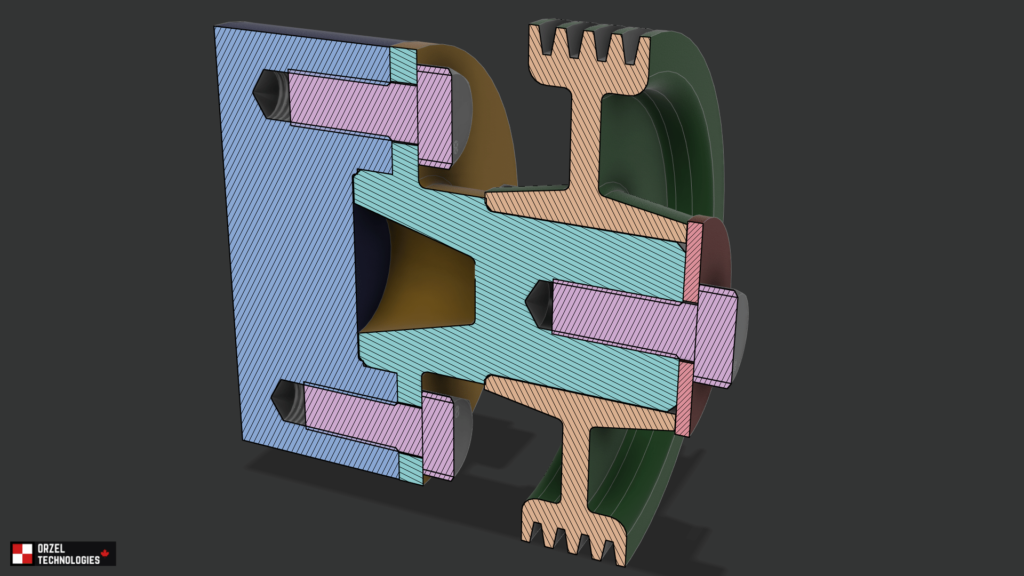
GD&T Examples – Datum Features: Establishing functional datums
We want our parts to go together correctly during assembly, for this reason we select corresponding interfacing features of mating parts as datum features. Although we won’t discuss it here, establishing functional datums can also significantly simplify tolerance stacks.
In our example as the four (4) bolts are installed and tightened the shoulder-surface of the spindle will contact the shaft’s end-face initially orienting the part; therefore, the shoulder surface is selected as the primary datum feature. Additionally, the bore of the shaft will guide the pilot of the spindle further reducing the degrees of freedom between the two parts; therefore, it is selected as the secondary datum. This simple example does not require a tertiary datum as the remaining rotational degree of freedom is constrained by the axially symmetric bolts. There are no other non-symmetric features such as keyways on the part that would need to be controlled for rotation.

GD&T Examples – Datum Features: Qualifying datum features
We have to remember that our part is never going to be perfect. The datum reference frame (i.e., the three mutually perpendicular planes) do not exist in reality. We therefore have to qualifying the real physical datum features.
Coming back to our example, the primary datum feature is qualified to itself (in our case flatness). Next, we qualify the secondary datum feature’s orientation relative to the primary datum. In our case we specify the perpendicularity relative to A. If we had a tertiary datum feature, we would qualify its orientations and/or location relative to the higher precedence datums.

GD&T Examples – Datum Features: Tolerance all of the remaining features
Once we have established and qualified our datums we tolerance every feature of our part. Although we haven’t applied tolerances to all of the remaining features in our example… we always want to do this to have a complete drawing. If certain features are not critical… just slap on a loose profile tolerance.

Conclusion
Although it might look confusing at first the geometric dimensioning and tolerancing system is a powerful tool that enables designers to accurately communicate design intent on a drawing. The system also facilitates the work of manufactures as well as quality engineers. All mechanical engineers, designers and drafts people should promote the use of GD&T on mechanical drawings to eliminate the ambiguity associated with plus/minus tolerancing.
Please share if you actively use GD&T at work in the comments below. If you have any GD&T questions please ask!
Subscribe to follow me on my journey to GDTP senior level certification.
Thank you for reading!
[…] Last week we talked about what I believe is the most important part of GD&T – picking function datum features. […]
[…] this post, we will be taking a break from Fusion360 and GD&T and we’ll be focusing on project management software. Over the next few posts, we will cover […]
Itís difficult to find knowledgeable people about this subject, but you sound like you know what youíre talking about! Thanks
I was excited to find this web site. I need to to thank you for ones time due to this wonderful read!! I definitely loved every little bit of it and I have you saved as a favorite to see new stuff on your site.